Ensuring fire pump efficiency
- September 28, 2023
- 8:00 am

Iain Hoey
Share this content
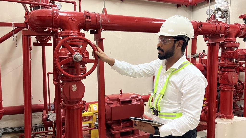
Amirtharaj Arun, Senior Testing Engineer at DCD’s Emirates Safety Laboratory, offers a comprehensive overview of the protocols and standards for fire pump testing
Fire pumps play a crucial role in firefighting systems, ensuring the safety of lives and preventing property damage.
It is essential to evaluate fire pump performance according to the manufacturer’s design specifications to ensure their effectiveness.
Various standards provide guidelines for testing and validating fire pumps, ensuring compliance with performance requirements.
The NFPA 20 standard guides fire pumps’ installation, commissioning, and acceptance, ensuring they meet the necessary life safety and building protection criteria.
These standards are essential references for meeting the demands and requirements of fire pump systems.
NFPA 20 Standard for the installation of pumps for fire protection
The fire pump consists of three key components: the pump itself, the drive system, and the controller, along with additional accessories.
The driver/driving system options include electric motors and diesel or internal combustion engines.
To ensure the proper installation of fire pumps in buildings and industries, NFPA 20 standards serve as a guiding framework.
Hydrostatic tests and flushing procedures are vital for maintaining the pump’s longevity and minimising the need for unscheduled maintenance.
During the field acceptance phase, it is essential to have system manufacturers or their representatives present to conduct the necessary tests and ensure the proper functioning of the fire pump system.
Flushing test
Before conducting fire pump tests and operation activities, it is crucial to complete flushing and hydrostatic testing.
The flushing test should be performed before the hydrostatic test, specifically focusing on the suction pipe.
As per the NFPA 20 standard, the flushing process must achieve a flow rate that is at least equal to or greater than the required value.
This required flow rate should equal or exceed 150% of the rated flow of the field pump.
In cases where the pump cannot provide a flow rate of 150% of its rated flow, the flushing flow rate should be set at a minimum of 100% of the pump’s rated flow.
These steps are essential for ensuring the proper functioning of the fire pump system.
Hydrostatic test
Hydrostatic testing plays a crucial role in maintaining the integrity of the fire pump system by removing any foreign particles that may have entered the suction inlet.
This process is essential to prevent damage to the impeller and ensure optimal pump performance.
The hydrostatic test guarantees the system’s pipes and fittings’ durability, quality, and safety.
This test minimises the risk of underground and aboveground pipeline system leakage, aligning with the guidelines specified in the NFPA 25 standard.
The field suction and discharge piping system should undergo a pressure test of not less than 200 psi or 50 psi above the maximum pressure to be maintained in the system.
The responsible installation contractor is responsible for providing a hydrostatic report before the fire pump acceptance test.
Furthermore, the pump manufacturer must perform a hydrostatic test on each pump before dispatch, adhering to the product’s standard requirements.
Electrical wiring of the pump system
Before the initial startup and acceptance test, a comprehensive inspection and verification of the wiring in all pump systems, including the jockey pump motor, electric motor, electrical drive pump, and diesel engine drive pump controller, were conducted.
This thorough process ensured that all system wiring, configurations, and connections were checked and verified.
It ensures that all connection terminals are correctly and securely tightened.
These measures were taken to mitigate electrical risks, such as shocks or arc flashing.
Electric fire pump controllers must also undergo an arc flash assessment following the NFPA 70E Standard for electrical safety in the workplace or the corresponding local approved standards.
Digital readout screens were utilised to measure current, voltage, and RPM to minimise the risk of electric shock or arc flash, eliminating the need to open the door for such measurements.
Flow test
During the flow test, the fire pump’s performance is measured and verified to ensure it meets the minimum requirements for rated head, flow, and peak power, as specified by the pump manufacturer’s certified plot and datasheet.
During this test, the critical consideration is ensuring that the system’s flow operates within the guidelines outlined in NFPA 20.
Suppose the water supply does not allow the pump to be operated at 150% of the rated flow: in that case, the pump must be operated at a minimum of its rated flow or at the highest demand of all the systems it serves, whichever is greater.
If the pump fails to achieve the desired performance during the initial acceptance test of a new installation, it could indicate that it is oversized relative to the available water supply.
The certified fire pump performance curve serves as the “birth certificate” of the fire pump, providing crucial information on how the pump will function in the field based on the manufacturer’s certified test curve.
This curve is a reference point to compare the pump’s performance in the field and ensure no damage occurred during transportation and setup.
The ultimate goal is to ensure the fire pump meets the required fire protection demand.
The pump manufacturer representative will set the start and stop pressures for the jockey and fire pump.
The stop pressure of the jockey pump is typically set close to the shut-off pressure setting range, although specific requirements are not defined.
Those overseeing the fire pump installation collaborate with the manufacturer’s representative to determine the appropriate start and stop pressures.
Field acceptance test
When conducting performance tests, it is essential to use measuring instruments calibrated per ISO 17025.
The fire pump should undergo testing at minimum, rated, and peak power loads, ensuring that the system components do not experience objectionable overheating.
Additionally, the vibration of the pump assembly should not reach a level that could potentially cause damage to any component of the fire pump system.
Determining the fire pump’s minimum, rated, and peak power loads involves controlling water discharge through calibrated test devices.
The flow rate of water discharged from the fire pump assembly will be precisely regulated and stabilised.
Furthermore, the fire pump’s suction is connected to a break tank, and the refill rates of the tank will be tested and documented.
These measures contribute to a comprehensive evaluation of the fire pump’s performance.
Additional testing
Following the flow test performance, several additional checks must be conducted to ensure the proper functioning of the fire pump system.
For diesel drivers, parameters such as engine speed, engine back pressure, oil pressure, cooling loop water pressure, and engine temperature must be monitored.
In the case of electric-driven motors, parameters such as motor speed, voltage, and amperes should be observed.
The representatives from the pump and driver manufacturers are responsible for verifying that these measurements align with the factory specifications.
All recorded data should be documented in the contractor’s material test certificate, providing a comprehensive record of the fire pump system’s performance and adherence to the required specifications.
Controller test
The controller test is a crucial step in the testing process, involving the repeated starting of the fire pump driver.
A total of six manual starts and six automatic starts are required during this test.
To initiate the pump, the control valve on the sensing line is automatically opened, causing the system pressure to decrease to the fire pump’s start point.
This simulation replicates the scenario where a sprinkler or other orifice device was open within the system.
By conducting this test, the functionality and response of the controller can be evaluated effectively.
Alternative power
When the fire pump is connected to an alternate power source, it is necessary to conduct a test that simulates a loss of the primary or regular power source.
This test is performed while the pump is operating at peak load.
The objective is to demonstrate that both the driver and pump can continue to function seamlessly using the alternative power source.
Furthermore, half of the automatic and manual starts should be carried out during the testing process while the pump is connected to the alternate power source.
This comprehensive evaluation ensures the reliability and effectiveness of the fire pump system under different power supply scenarios.
Evaluating test results
Evaluating the test results is paramount to ensuring the fire pump system meets the required qualifications.
The fire pump acceptance test involves comparing the test results against the certified pump curve, including documenting the project name, installation location within the project site and the pump’s serial number in the acceptance test report.
During this evaluation, various parameters need to be reviewed, such as suction and discharge flow, pressure, rated speed capacity, total head for vertical and horizontal pumps, electrical input, and any RPM correction to the rated speed.
Once the flow test is completed, the results are plotted on a graph to compare them with the manufacturer’s certified pump curve visually.
The graphical representation assesses how the recorded test results align with the expected performance.
This evaluation ensures the fire pump system meets the requirements and operates within the desired parameters.
Document completion
As part of the final acceptance process, NFPA 20 mandates the submission of specific documentation for the fire pump system.
This includes one set of record drawings of the fire pump system, one copy of the completed acceptance test report, and a critical equipment electrical drawing.
One set of detailed instruction manuals for all major fire pump system components must also be provided.
For more efficient scrutiny, testing, and upkeep, it is suggested to have a copy of NFPA 25.
These documents are essential for the building owner to have a comprehensive understanding of the fire pump system and to ensure proper ongoing operation, maintenance, and compliance with applicable standards.